OSPF Incremental SPF (iSPF)

In today’s post, we will talk about one very cool feature in OSPF.   As you know, OSPF uses the Dijkstra’s algorithm to calculate the shortest path tree or SPT and create a topology graph.   This topology is then used to populate the routing table.

Now, when a change occurs in the network, link-state advertisements (LSAs) are flooded to inform all members of a given area about the changes.   When a change to a Type-1 or Type-2 LSAs occurs in an area, the entire SPT has to be recalculated. This is the normal behavior of OSPF.  Now, the problem arises in cases where the change affects only to a small section of the tree.    In this particular scenario, there is no need to recalculate the entire SPT because most of the SPT remain unchanged.    Here is where ISPF enters to play.

Incremental SPF allows the recalculation of the affected area without the overhead caused from full SPF recalculation as long as the affected link is a leaf in the SPT.   The result is faster convergence and the reduction of CPU utilization.

Configuring ISPF

To configure ISPF use the ispf OSPF process command.

Worth mentioning that routers with ISPF configured can operate with routers without this feature enabled.

It is time to close this post.  In the next one, we will discuss some additional OSPF features.

Thank you for visiting.

OSPF Pacing Timers

In our previous post, we discussed how OSPF can be tuned to prevent frequent computation of the SPF in times of network instability by using OSPF throttling.

By using this scheduling technique, if a large number of LSAs are received, triggered by events such a link or OSPF neighbor down, the SFP rather than immediately start the SFP calculation for every received LSA it will wait for more LSAs to be added to the LSDB before triggering the SFP calculation.

This solution is suitable for this situation, but what about self-originated such the aged-out or corrupted (like the ones with invalid checksum) LSAs?

There is where LSA and SPF pacing enters to play.   Before going into detail, let me emphasize something:  Modifying the OSPF timers is not recommended unless you fully understand and know what you are doing.   The incorrect tuning or long timers of SPF pacing may lead to slow convergence.

Now that you were warned let’s talk about it.

Since IOS version 12.2, Cisco has introduced three types of packet-pacing delay timers to optimize the LSA flooding procedure.

  • Group packet-pacing timer
  • Flood packet-pacing timer
  • Retransmission packet-pacing timer

OSPF Group packet-pacing Timer

In Cisco implementations of OSPF (before Cisco IOS 12.0), the aging of every LSA’s was individual, meaning that only LSAs close to 1800 seconds were re-flooded.   This process was better than the original “full” refresh done every 30 minutes, but still inefficient because it produces multiple quick floods due to independent aging during the interval.   The Group packet-pacing timer, instead of processing independent LSAs, group the ones ready to be refreshed and flood them all at once every 240 seconds by default.

To configure the OSPF group packet-pacing timer use the timers pacing lsa-group {seconds} OSPF process command.

OSPF Flood packet-pacing Timer

The flood pacing timer operates on a per-interface basis; it applies only if a router has more than a single LSA to be flooded out an individual interface.   The way it works is that if a router has a large number of LSAs to be flooded out an interface, the timer will prevent flooding the LSAs immediately one after the other one. Instead, it’s added to the flooding list. Then after 33 milliseconds (default packet-pacing timer), the LSAs included in the list are flooded.

To configure the OSPF flood packet-pacing timer use the timers pacing flood {milliseconds} OSPF process command.

OSPF Retransmission packet-pacing Timer

This timer works the same way as group packet-pacing timer but only takes care of the unacknowledged LSAs.   In other words, if an LSAck is not received, the LSA is placed in a flooding list instead flooding the LSA at once.   The default timer in Cisco implementations is 66 milliseconds.

To configure the OSPF flood packet-pacing timer use the timers pacing retransmission {milliseconds} OSPF process command.

It is time to close this post.  In the next one, we will discuss OSPF incremental SPF.

Thank you for visiting.

OSPF LSA & SPF Throttling

The biggest challenge in large-scale networks is to recover quickly from failures and instability.

As you know, OSPF is a link-state protocol which uses LSAs to advertise topology changes to other OSPF-enabled routers.    When this happens, OSPF runs the SPF algorithm.

The problem arises when LSAs are received too quickly due network instability; in this case, the SPF calculation has to run whenever a new LSA arrives (LSA-driven), this may result in high CPU utilization.   Here is where SPF throttling enters to play.

OSPF SPF throttling

OSPF throttling is a scheduling technique used to delay SPF calculations by imposing an SPF-waiting interval.  With this interval in place, if a large number of LSAs are received, SPF rather than immediately trigger the SFP calculation, it waits for LSAs to be added to the Link-State Database (LSDB).   Then when the SPF-waiting interval expires, SPF calculation runs.   This result in more changes included in a single calculation.     Using this timer naturally increases the efficiency of OSPF; however, this solution has a side effect:  It also increases the convergence time.

The ideal solution would have a long wait interval when the network is unstable and short when it’s operating in the normal way.  Some SPF adaptive timers.

Well, we are lucky; Cisco introduced an exponential back-off algorithm since IOS Release 12.2 which use three additional timers to the waiting timer interval to achieve this  (All three timers are displayed as delay in the CLI, thus I will assign different names to each one for easy understanding):

  • SPF-start: Indicates the initial SPF schedule delay. By default, the SPF-start timer is 5000 milliseconds.
  • SPF-hold: Indicates the minimum hold time between two consecutive SPF calculations. By default, the SPF-hold timer is 10000 milliseconds.
  • SPF-max: Indicates the maximum wait time between two consecutive SPF calculations. By default, the SPF-maximum timer is 10000 milliseconds.

These timers are expressed in milliseconds, and all of them have a range from 1 to 600,000 milliseconds.

To configure OSPF SPF Throttling use the timers throttle spf {SPF-start} {SPF-hold} {SPF-max} OSPF process command.

Here is how it works:

When the first LSA is received, the SPF calculation is delayed for the value set by the SPF-start timer.  The SPF-waiting timer is set to the value of the SPF-hold timer.

LSA(1) - (SPF-start=5000) (SPF-hold=1000) –> (SPF-waiting= SPF-hold)

If the router receives more LSAs during the SPF-waiting timer, the SPF-waiting interval is set to the twice of its value.  The SPF-waiting interval will increment every time an event occurs during the current hold-time window.

LSA(2) - (2*SPF-wait=20000)
LSA(3) - (2*SPF-wait=40000)
LSA(4) - (2*SPF-wait=80000)

The SPF calculation will be delayed until the current SPF-hold timer expires; if not, the SPF-wait interval will continue growing exponentially until it reaches the SPF-max value.   If this happens, then the SPF calculation will take place.

If there are no more events for two times the SPF-max timer, timers will be reset back to the configured timer values.

OSPF LSA throttling

This feature also provides a dynamic scheduling to slow down the frequency of LSA generation during network instability.    Before this feature was introduced, the LSA generation was rate-limited for 5 seconds; this is the default LSA-wait timer interval.   That meant that the LSA could not be propagated in milliseconds. Therefore, OSPF could not achieve sub-second convergence.   The principle is similar to the SPF throttling.   It provides Adaptive Timers for LSA generation when the network is unstable.

OSPF LSA throttling also uses three additional timers to the waiting timer interval to achieve this (All three timers are displayed as delay in the CLI, thus, I will assign different names to each one for easy understanding):

  • LSA-start: Indicates the initial LSA generation schedule delay. By default, the LSA-start timer is 0 milliseconds.
  • LSA-hold: Indicates the minimum hold time between two consecutive LSA calculations. By default, the SPF-hold timer is 5000 milliseconds.
  • LSA-max: Indicates the maximum wait time between two consecutive LSA calculations. By default, the LSA-max timer is 5000 milliseconds.

To configure OSPF LSA Throttling use the timers throttle lsa all {LSA-start} {LSA-hold} {LSA-max} OSPF process command.

Here is how it works:

By default, the first LSA is sent immediately after an event occurs; then the LSA-wait timer is set to LSA-hold interval.

LSA(1) – (LSA-start=0) (LSA-hold=5000) –> (LSA-waiting= LSA-hold)

If additional LSAs needs to be generated, it will at the LSA-hold interval, then the LSA-wait interval is set to the twice of its value.

LSA(2) – (2*LSA-wait=20000)

LSA(3) – (2*LSA-wait=40000)

LSA(4) – (2*LSA-wait=80000)

If there are several events during the LSA-waiting interval, the LSAs will be grouped and sent when the LSA-hold timer interval expires.   The LSA-wait interval will continue growing exponentially until it reaches the LSA-max value.   If this happens, then the grouped LSAs will be generated.

If there are no more events for two times the LSA-max timer, all timers will be reset back to the configured values.

When using OSPF LSA Throttling it’s also required set the minimum interval for accepting the same LSA.    Let me explain this:   If the same LSA arrives sooner than the interval that is set, the LSA is dropped.    Now, Cisco recommends the arrival interval be less than or equal to the LSA-hold timer interval of the timers throttle lsa all command.

To do so use the timers lsa arrival {milliseconds} command.

Let’s use the following topology for the examples:

OSPF-SPF-THROTTLING-01

Here you can download the diagram and configuration files: OSPF-Throttling

Example 1:

Let’s configure SPF throttling with an initial delay of 5 milliseconds and hold timer of 10 seconds and an expiration of 90 seconds on both routers.

In R1& R2:

!
router ospf 1
timers throttle spf 5 10000 90000
exit
!

Ok, now both routers have the SPF throttling configured as shown next:

OSPF-SPF-THROTTLING-02

OSPF-SPF-THROTTLING-03

Let’s test the configuration.   To do so, let’s flap the loopback 0 interface in R2.


Before start flapping the interface let’s enable the spf statistics debugging to observe the changes.  I never get tired of saying that debug should be used with caution.

In R1& R2:

!
debug ip ospf spf statistic
!

Let’s flap the interface several consecutive times with the shutdown/no shutdown interface command.

OSPF-SPF-THROTTLING-04


As can be seen in the above output, the configuration worked as expected.  When R1 first detects the topology change, it initiated SPF calculation after 5msec, when the router detected the second topology change it waited 10000msec and it set the next waiting interval was set to the twice of its value (20000) and continue growing.  Once the wait interval reaches the maximum wait interval 90000msec, the wait interval remains the same until the network stabilizes.

Let’s clear the debug and the previous configuration for the next example.

In R1& R2:

!
no debug ip ospf spf statistic
!
config t
!
router ospf 1
no timers throttle spf 5 10000 90000
exit
!

Example 2:

Let’s configure LSA throttling with an initial delay of 100msec and hold timer of 10 seconds and an expiration of 50 seconds on both routers.  Set the LSA arrival interval to 2 seconds.

In R1 & R2:

!
router ospf 1
timers throttle lsa all 100 10000 50000
timers lsa arrival 2000
exit
!

Ok, now both routers have the LSA throttling configured as shown next:

OSPF-LSA-THROTTLING-05

OSPF-LSA-THROTTLING-06

Let’s test the configuration.   To do so, let’s flap again the loopback 0 interface in R2.

Before start flapping the interface let’s enable the database-timer rate-limit debugging in R2 to observe the changes.

In R2:

!
debug ip ospf database-timer rate-limit
!

Let’s flap the interface several consecutive times with the shutdown/no shutdown interface command.

OSPF-LSA-THROTTLING-07

As can be seen in the above output, the configuration worked as expected.  The interface was shut down, which causes OSPF to generate a new Type-1 LSA, then the next wait timer was set to 10000ms.  Then, a new change is detected; therefore, the next wait timer was set to 20000ms.

It is time to close this post.  In the next one, we will discuss the OSPF Pacing Timers.

Thank you for visiting.

OSPF Stub Router Advertisement and Graceful Shutdown

The OSPF Stub Router Advertisement feature is used to gracefully shut down or reload an OSPF-enabled router without dropping packets using the router as transit to reach other networks.

This feature is also used to bring a new OSPF-enabled router to the network without immediately start routing traffic through it.

The way it works is that when Stub Router Advertisement is configured, the router will originate LSAs with the max-metric set through all transit links.  This cause the OSPF neighbors assign a higher cost to the router; therefore, they will use alternate paths to reach networks passing through the router.

OSPF Stub Router Advertisement at Startup:

Configuring this feature when the router is started or reloaded is used to force neighbor routers to use alternate paths while a defined timer expires.    This is helpful because it allows the routing table to converge before traffic is sent through the router.   This improves the stability of the network.

To configure OSPF Stub Router Advertisement on Startup use the max-metric router-lsa on-startup <announce-time> OSPF process command.   The announce-time parameter is a configurable timer which goes from 5 to 86,400 seconds.

This feature can also be used in situations where the router to be reloaded also receive routes from BGP.    IGPs converge very quickly, and most of the times before BGP, therefore, if an OSPF neighbor router forwards traffic through the recently reloaded router before BGP has converged, these packets may be dropped.

To configure OSPF Stub Router Advertisement in situations where is required waiting for BGP convergence, use the max-metric router-lsa wait-for-bgp OSPF process command.  By using this feature, OSPF will advertise max-metric through all transit links until BGP routing table has converged or until the default timer has expired.  The default timer is 600 seconds.

OSPF Stub Router Advertisement for Graceful Shutdown:

This feature is used in situations where is necessary removing a router from the network.  Without using this feature, if a non-directly connected OSPF-enabled router is removed from the network, the OSPF neighbors will wait for the dead timers to expire before the adjacency and the routing tables reconverge.   Some packets may be dropped while the routing tables reconverge.  Therefore, advertising max-metric before shutdown allows other neighbors to use alternate paths before the transit router becomes inaccessible.

To configure OSPF Stub Router Advertisement for Graceful Shutdown use the max-metric router-lsa OSPF process command.    Keep in mind not to save the configuration after Graceful Shutdown was configured because the router will continue advertising max-metric after the router was turn on.

Let’s use the following topology for the examples:

OSPF-Stub-RA-01

Here you can download the diagram and configuration files: OSPF-Stub-RA

About the topology:

All routers have loopback0 interface configured (not shown in the diagram) as follows:   Lo0 in R1 has 1.1.1.1/33, R2 has 2.2.2.2/32, and R3 has 3.3.3.3/32 and so on.   The loopback interfaces are advertised into OSPF.   R4 has OSPF Stub Router Advertisement configured with a timer set to 300 seconds (5 minutes) with the command max-metric router-lsa on-startup 300.

Before R4 was shut down, the OSPF process is showing the Stub Router Advertisement feature inactive as shown next:

OSPF-Stub-RA-02

From the perspective of R5, the route to the transit network 192.168.12.0/24 it’s been load balanced between R3 and R4.

OSPF-Stub-RA-03

Ok, it’s time to turn on R4 and let’s see what happens.

First, let’s check the OSPF process:

OSPF-Stub-RA-04

As can be viewed in the above output, the OSPF Stub Router Advertisement is now active; it also shows the timer with 4 minutes and 40 seconds left before the router start advertising the LSAs without the maximum metric value.

Now let’s take a look to the router LSAs (Type-1) in R4.  Let’s use the show ip ospf database router self-originate command for this purpose.

OSPF-Stub-RA-05

As can be seen in the output, the Type-1 LSAs corresponding to the transit networks in R4 have the max-metric set.   This is also known as LSInfinity.   Also, note the metric of the loopback0 interface remain as 1.   This is because stub router advertisement only affects to non-stub networks.  Despite the transit networks have the metric set to LSInfinity; the stub networks still have reachability to the rest of the network as shown next:

OSPF-Stub-RA-06

Finally from the perspective of R5, the previous load balanced path to the segment 192.168.12.0/24 is now only via R3 as shown next.

OSPF-Stub-RA-07

After the timer had ended, the transit routes through R4 were advertised to the neighbors with normal LSAs and the OSPF Stub Router Advertisement feature went to the inactive state.

Now it is practically the same example when is required waiting for BGP routes to converge using the command max-metric router-lsa wait-for-bgp.  The difference is that this feature will go to the inactive state if BGP fully converges and start redistributing routes into OSPF or the default timer of 600 seconds expires, whichever comes first.

Now, let’s configure OSPF Graceful Shutdown in R3.

In R3:

!
router ospf 1
max-metric router-lsa
exit
!

Immediately after the command was entered, the OSPF Stub Router Advertisement was triggered with the condition set to always as shown next:

OSPF-Stub-RA-08

Now it’s possible to turn off the router without much problem because transit traffic no longer passes through R3.   Other neighbors are receiving the LSAs with the LSInfinity set.   Remember not to save the configuration after this feature was configured because the router will continue advertising max-metric after the router was turn on.

To confirm the configuration let’s take a look to the Type-1 LSAs in R3:

OSPF-Stub-RA-09

As can be seen in the above output, the self-originated Type-1 LSAs in R3 have the metric of the transit networks set to LSInfinity.   The cost of the stub networks remains the same.

In newer IOS version, is possible to extend this behavior to stub networks using the command max-metric router-lsa include-stub.

It is time to close this post.  In the next one, we will discuss OSPF LSA & SPF Throttling.

Thank you for visiting.

OSPF Conditional and Reliable Conditional Default Routing

In the previous post, we learned how to configure OSPF default routing and the rules that apply to its configuration.

Today we will discuss the enhancements that can be applied to OSPF Default Routing.

Ok, so far we know that the “default-information originate” command is used to generate a default route into the OSPF domain.    If the default route is not present in the routing table, then it won’t be generated.  However, we can modify this behavior by adding the “always” keyword at the end of the command.

Now, there are situations when is required generating the default route only if a condition matches specific criteria.   There is where OSPF Conditional Default Routing enters to play.

Let’s use the following topology for the examples:

OSPF-CONDITIONAL-DR-01

Here you can download the diagram and configuration files:  OSPF-Default Routing II

OSPF Conditional Default Routing:

OSPF Conditional Default Routing is configured by adding a pre-defined route-map with the desired conditions to the default-information originate command in the OSPF process definition.

By using route map its possible defining matching conditions such as:

  • Match if a specific ip address or prefix is present in the routing table.
  • Match if the source of a specific ip address or prefix is a specific ip address or interface.
  • Match if the source protocol of a specific address or prefix is an IGP or static route or connected.
  • Match if the route type is external (E1/E2), internal (Intra/inter-area), nssa-external or locally originated.
  • Match the metric value of a specific address or prefix with a specified value.

Combinations of the conditions described above are also possible.

Ok, time for the examples.

First, let’s take a look to the routing table in the OSPF domain:

OSPF-CONDITIONAL-DR-02

OSPF-CONDITIONAL-DR-03

OSPF-CONDITIONAL-DR-04

As can be seen in the above outputs, R1 has routes from R2 and R3.  It also has the route 4.4.4.4/32 redistributed from EIGRP.   The routers R2 and R3 are receiving the default route generated by R1.   Both routers also have the external routes redistributed from EIGRP.

Goal 1:

Configure OSPF default routing in such way that R2 and R3 receive the default route from R1 only if the route 4.4.4.4/32 is present in the routing table.

Let’s proceed with the configuration:

In R1:

!
ip prefix-list L0-R4 seq 5 permit 4.4.4.4/32
!
route-map CONDITIONAL-DEFAULT permit 10
match ip address prefix-list L0-R4
!
router ospf 1
default-information originate always route-map CONDITIONAL-DEFAULT
exit
!

The above configuration permits the default route to be originated in OSPF only if the route 4.4.4.4/32 is present in the routing table.

Because the prefix 4.4.4.4/32 currently exists in R1’s routing table, then the default route is generated.

Now, let’s stop the advertising of the Loopback 0 in R4 and check the routing table in R2 to verify if the condition works.

In R4:

!
router eigrp 100
no network 4.4.4.4 0.0.0.0
exit
!

OSPF-CONDITIONAL-DR-05

As can be seen in the above output, now the default route is no longer present in the routing table.

Goal 2:

  1. Configure a static default route in R1 pointing to R4.
  2. Configure OSPF default routing in such way that R2 and R3 receive the default route from R1 only if the link to R4 is up.

First, let’s clear the previous configuration in R1 and create the static default route.

In R1:

!
router ospf 1
no default-information originate
default-information originate
exit
!
no ip prefix-list L0-R4 seq 5 permit 4.4.4.4/32
no route-map CONDITIONAL-DEFAULT permit 10
!
ip route 0.0.0.0 0.0.0.0 192.168.14.2
!

Now, to verify if the interface is in UP/UP status, what can be done is check if the “Connected” route is in the routing table.   If a Layer 2 failure occurs with the connection to R4, then the connected route is removed from the routing table.

OSPF-CONDITIONAL-DR-06

Let’s configure the condition:

In R1:

!
ip access-list standard ETH-01-UP
permit 192.168.14.0 0.0.0.255
exit
!
route-map CONDITIONAL-DEFAULT permit 10
match ip address prefix-list L0-R4
exit
!
router ospf 1
default-information originate route-map CONDITIONAL-DEFAULT
exit
!

The above configuration permits the default route to be originated in OSPF only if the connected route 192.168.14.0/24 is present in the routing table.  If there is a Layer 2 failure, then the default route won’t be generated.

To test the above configuration I’ll disconnect the cable connecting to R2 and then I’ll check the routing tables in R1 and R2 respectively.

OSPF-CONDITIONAL-DR-07

OSPF-CONDITIONAL-DR-08

As can be seen in the output, as soon the interface in R1 was disconnected from R1, “connected” route 192.168.14.0/24 was removed from its routing table.   This means that the condition configured before does not match the requirements anymore.  Thus, the default route is no longer advertised to R2 and R3.

Pretty cool, huh?   The configuration worked as expected in this situation.

Now, what if is not a Layer 2 failure?  In other words, let’s say the interface remains up but there is no connectivity to the desired destination through it?

Well, in this type of situations is where Reliable Conditional Default Routing enters to play.

OSPF Reliable Conditional Default Routing:

OSPF Reliable Conditional Default Routing this is achieved through the combination of Conditional Default Routing and Cisco IP SLA with Enhanced Object Tracking (EOT).

Goal 3:

Configure OSPF default routing in such way that R2 and R3 receive the default route from R1 only if there is end-to-end reachability to R4.

Let’s start by removing the previous configuration in R1.

In R1:

!
router ospf 1
no default-information originate
default-information originate
exit
!
no ip access-list standard ETH-01-UP
no route-map CONDITIONAL-DEFAULT permit 10
no ip route 0.0.0.0 0.0.0.0 192.168.14.2
!

Ok, the next step is configuring the IP SLA.

In R1:

!
ip sla 1
icmp-echo 192.168.14.2
threshold 3000
timeout 4000
frequency 5
exit
!
ip sla schedule 1 life forever start-time now
!

The above configuration created the ip sla entry 1, which will send icmp packets every 5 seconds to the ip address 192.168.14.2 (interface Ethernet0/1 of R4) with a threshold of 3 seconds and timeout of 4 seconds.  The scheduling has enabled the ip sla entry 1 with no expiration.

The next step is configuring the Enhanced Object Tracking.

In R1:

!
track 1 ip sla 1 reachability
!

Let’s stop here and take a look to the IP SLA and the Enhanced Object Tracking status.

OSPF-CONDITIONAL-DR-09

OSPF-CONDITIONAL-DR-10

As can be seen in the above outputs, the IP SLA is working and returning success operation.   Also, the Enhanced Object Tracking is returning “UP” reachability status.

Let’s continue.

Now that we have the IP SLA and the Enhanced Object tracking configured, we have to create the condition.

Now, for the condition to work, we will need something to match. Right?

The next step is configuring a placeholder to create a prefix in the routing table and use the enhanced object tracking to validate this route.

In R1:

!
ip route 169.255.0.4 255.255.255.255 Null0 track 1
!

The above configuration created a default route for the ip address 169.255.0.4 (link-local RFC 6890) pointing to the trash can.   The track 1 command forces the route to remain valid while the enhanced object tracking returns reachability UP.

OSPF-CONDITIONAL-DR-11

As can be seen in the above output, the placeholder is working.   The prefix 169.255.0.4/32 is present in the routing table because the enhanced object tracking is returning UP status.

Let’s shut down the interface Ethernet0/1 in R4 and let’s take a look at the routing table again.

In R4:

!
interface Ethernet0/1
shutdown
exit
!

OSPF-CONDITIONAL-DR-12

As can be seen in the above output, the enhanced object tracking changed the status to Down, also, the prefix 169.255.0.0/32 was removed from the routing table.

Let’s enable back the interface in R4.

In R4:

!
interface Ethernet0/1
no shutdown
exit
!

OSPF-CONDITIONAL-DR-13

As can be seen in the above output, the placeholder is working as expected.

Now we have to configure the route-map and attach it to the default-information originate command.

In R1:

!
ip prefix-list PLACEHOLDER seq 5 permit 169.255.0.4/32
!
route-map R-C-DEFAULT permit 10
match ip address prefix-list PLACEHOLDER
!
router ospf 1
default-information originate always route-map R-C-DEFAULT
exit
!

The above configuration permits the default route to be generated if the prefix 169.255.0.4/32 (Placeholder) is present in the routing table.   The always keyword was used because the default route was not present in the routing table.

Finally, let’s shut down again the interface Ethernet 0/1 in R4 and check the routing table in R2:

In R4:

!
interface Ethernet0/1
shutdown
exit
!

OSPF-CONDITIONAL-DR-14

As can be seen in the above output, after the interface was disabled in R4, the default route was removed in R2.    The OSPF Reliable Conditional Default Routing was properly configured.

It is time to close this long post.  In the next one, we will discuss OSPF Stub Router Advertisement.

Thank you for visiting.

OSPF Default Routing


In today’s post, we will discuss the different ways in which OSPF generates the default oute.

Long story short, it depends on the type of area where we want to generate or advertise the default route.

Let’s get started by describing how to generate and advertise the default route per area and the rules that must be followed if any.   Maybe it would be a good idea to check out the post OSPF Areas and Area Types for better understanding.

Normal Areas:

The default route is not advertised by default in normal areas, even if one exists in the routing table.   The way to generate the default route in normal areas is by using the default-information originate {always} {metric [value]} {metric-type [type-value]} {route-map [map-name]} command in the OSPF process definition.

As a rule, the default-information originate command will advertise the default route only if it exists in the routing table.  If we don’t have a default route configured, then the keyword always can be added to override this rule.

Another way to override this rule is by creating a default route pointing to the null0 interface.  Thus, the default route will be installed in the routing table.

With the keywords metric and metric-type, it’s possible specifying the metric and the metric-type of the default route.    The default metric is 1 and the default metric type is 2.

The keyword route-map is used to extend the capabilities of default routing by the use conditions or adding reliability mechanisms into it.

In this type of areas, the LSA generated for the default route is Type-5.

Stub and Totally Stub Areas:

In this type of areas, the ABR automatically generates a summary LSA (type-3) with the default route.   In this area types, is not necessary to use the default-information originate command.

NSSA Areas:

In NSSA, the default route is not advertised by default.   The way to generate the default route in NSSA is by adding the default-information originate {metric [value]} {metric-type [type-value]} {nssa-only} command at the end of the NSSA definition in the OSPF process definition.

In NSSA, the default-information originate command will advertise the default route to the NSSA area regardless if the route exists or not in the routing table only if is configured in the ABR connecting to the NSSA.   This is not the case for internal NSSA routers (non-ABR/ASBR) which requires the default route present.

If OSPF default routing is enabled in an internal NSSA router, it will generate a Type-7 LSA corresponding to the default route, and then the Type-7 LSA will be translated into a Type-5 LSA by the ABR or the elected Type-7/5 translator and then flooded to the rest of the OSPF domain.   To suppress the propagation of the default route beyond the ABR, the keyword nssa-only must be used.

With the keywords metric and metric-type, it’s possible specifying the metric and the metric-type of the default route.    The default metric is 1 and the default metric type is 2.

In this type of areas, the LSA generated for the default route is Type-7.

Totally NSSA:

In this type of areas, as in stub and totally stubby areas, the ABR automatically generates a summary LSA (type-3) with the default route.   In this area types, is not necessary to use the default-information originate command.

One last thing I should mention is that generating the default route in Normal or Not-So-Stubby Areas, will turn the router into an ASBR.

Let’s use the following topology for the examples:

OSPF-DEFAULT-ROUTING-01

Here you can download the diagram and configuration files: OSPF-Default Routing

Example #1:

Configure OSPF default routing in such way that R4 and R5 receive the default route from R1 with a metric of 20.

The configuration in R1 doesn’t have any default route configured at this moment; therefore, it can be done in two ways:

The first one is adding the keyword always when generating the default route.

In R1:

!
router ospf 1
default-information originate always metric 20
exit
!

Let’s take a look to the routing table of R4 and to the LSDB:

OSPF-DEFAULT-ROUTING-02

As can be seen in the above output, the route was generated by R1 as External Type-2 with a Metric of 20.    External Type-2 routes are the ones where the cost is equal to the cost from the ABR (R1 ABR/ASBR in this case) to the prefix destination.   External Type-1 routes are the ones where the cost is additive.   In other words, it’s the cost to reach the ABR from the source, plus the cost from the ABR/ASBR to the prefix destination.

The second way to do this is by creating a default route pointing to null and then generate the default route.

First, let’s remove the previous command.

In R1:

!
router ospf 1
no default-information originate
exit
!

Now let’s configure a default route and advertise it into OSPF.  (To demonstrate the change, I will not alter the metric.)

In R1:

!
ip route 0.0.0.0 0.0.0.0 null0
!
router ospf 1
default-information originate
exit
!

Let’s check again the routing table of R4 and the LSDB:

OSPF-DEFAULT-ROUTING-03

As can be seen in the above output, the default route was generated by R1 as External Type-2 with a Metric of 1, which is the cost from R1 (ABR/ASBR) to its Null0 interface.

Example #2:

Configure OSPF default routing in R2 and advertise the default route to the entire OSPF domain.

Ok, first let’s clear the previous configuration.

In R1:

!
no ip route 0.0.0.0 0.0.0.0 null0
!
router ospf 1
no default-information originate
exit
!

Let’s apply the configuration:

In R2:

!
ip route 0.0.0.0 0.0.0.0 null0
!
router ospf 1
area 123 nssa default-information-originate
exit
!

Let’s take a look to the routing table of R1 and to the LSDB:

OSPF-DEFAULT-ROUTING-04

As can be seen in the above output, the default route was advertised by R2.  Also, note R2 generated a Type-7 LSA for the advertised default route; the ABR (R1) then generated a Type-5 LSA and flooded to the rest of the OSPF domain.  Therefore, the default route will be also present in R4 and R5.

To confirm this, let’s take a look at the routing table in R5:

OSPF-DEFAULT-ROUTING-05

Ok, it worked, but what if the requirement includes that the default route should be advertised only within the NSSA area?

In this case, just add the keyword nssa-only to the previous configuration.

In R2:

!
router ospf 1
area 123 nssa default-information-originate nssa-only
exit
!

Let’s take a look again at the routing table in R5:

OSPF-DEFAULT-ROUTING-06

What happened here was that when R2 generate the Type-7 LSA was without the P-bit set. Therefore, the translation did not take place in R1 (ABR), as can be seen in the next output:

OSPF-DEFAULT-ROUTING-07

It is time to close this post.  In the next one, we will discuss OSPF Conditional Default Routing.

Thank you for visiting.

OSPF LSA Database Filtering and Flood Reduction

By design, OSPF implementations in Cisco devices refresh their LSAs every 30 minutes by default.  If the LSA reaches its max age (3600 seconds), it will be discarded.  If a router receives a new OSPF LSA, it will flood it over all interfaces belonging to the same area, except through the interface from where the LSA was received.

There are some topologies in which this behavior may result in unnecessary waste of bandwidth or network instability due excessive link use and CPU processing.

OSPF provides two different techniques that can be used to solve issues like the one described above:

OSPF database-filter:

With OSPF database-filter is possible the blocking of LSA flooding in the outbound direction.   To configure this feature use the command ip ospf database-filter all out to the interface that connects to the area to be filtered.    This command can also be used to block LSA flooding to specific neighbors in point-to-multipoint networks.  This is achieved by using the OSPF process command neighbor {ip-address} database-filter all out, where the ip address is the one assigned to the interface connecting to the area, not be confused with the neighbor’s router-id.

OSPF flood-reduction:

With OSPF flood-reduction, the unwanted flooding is achieved by setting the DoNotAge (DNA) bit in the LSAs, therefore, the LSAs do not have to be refreshed every 30 minutes.    To configure this feature use the ip ospf flood-reduction command to the desired interface.

When any of the above-described techniques is configured on an already established neighbor relationship, the adjacency will flap.

Let’s use the following topology for the examples:

OSPF-LSA-DB-FILTERING-01

Here you can download the diagram and configuration files: OSPF-Filtering – Part V

As can be seen in the diagram, the backbone area is connecting to Area 145 via a frame-relay cloud.  The connectivity in the frame-relay cloud was configured as hub and spoke, where R1 is the hub.

Let’s start playing with filtering.

Goal 1:

Configure OSPF filtering on R1, in such way that LSAs towards area 145 are blocked.  After the change was done verify connectivity to the network.

Ok, before applying the filter; let’s take a look at the LSDB to one of the spokes.  (Remember, routers in the same area have identical copies of the LSDB, therefore, both spokes have an exact copy of the LSDB.)

OSPF-LSA-DB-FILTERING-02

As can be seen in the output, the current state of the database is stable, the LSDB contains Type-1 LSAs corresponding to R1, R4, and R5 respectively in Area 145, also is possible find Type-3 LSAs corresponding to the summary networks advertised by R1 (ABR); and finally, Type-7 LSAs corresponding to the redistributed loopbacks in R4 and R5 and the default route originated in R1.

Next, let’s take a look to the routing table in R4:

OSPF-LSA-DB-FILTERING-03

As can be seen in the output, the routing table in R4 perfectly reflects the prefixes found in the LSDB:  Intra-Area (O) routes corresponding to the Type-1 LSAs, Inter-Area Routes (O IA) corresponding to the Type-3 Summary LSAs and NSSA External (O N2) which corresponds to the Type-7 LSAs.

Now, let’s take a look from R1’s perspective.

First, from the LSDB:

OSPF-LSA-DB-FILTERING-04

Ok, as can be seen in the above output, R1 has two views in its LSDB, one for each area respectively plus the Type-5 LSAs generated to advertise the redistributed routes coming from R4 and R5 in the NSSA.

Now let’s take a look to the routing table in R1:

OSPF-LSA-DB-FILTERING-05

As can be seen in the output, R1 has OSPF intra-area routes for the loopbacks in R2 and R3 in area zero (0).  Because R1 is the ABR connecting area 145, it also has NSSA External routes for the redistributed routes from R4 and R5.   From the perspective of R2 or R3 for example, these routes instead NSSA External (Type-7 LSA) would be OSPF External (Type-5 LSAs).   It is the same case for the intra-area routes corresponding to the serial1/0 interfaces of R4 and R5; they were advertised as Type-1 LSAs because R1 has the Serial1/0 interface participating in the NSSA area, thus, the routes were advertised via Type-1 LSA.  From the perspective of R2 or R3, these routes instead intra-area would be OSPF summary (Type-3 LSAs) routes.

Ok, now that we have verified the LSDB status, let’s apply the filter:

In R1:

!
interface Serial1/0
 ip ospf database-filter all out
exit
!

Immediately after the command was entered in the interface, the adjacencies with R4 and R5 were torn down and then re-established as shown next:

OSPF-LSA-DB-FILTERING-06

What was the result of this configuration?

Let’s check the LSDB in R4:

OSPF-LSA-DB-FILTERING-07

As shown in the above output, apparently nothing happened.   Well, this is not entirely true.  With this command, you cannot see immediate results.   As a matter of fact, now that the filter was applied and the LSAs refresh is no longer taking place, you have to wait until the LSAs age value reaches 3600 seconds (Max-Age value).   Remember, Cisco OSPF-enabled routers refresh LSAs every 1800 seconds (1/2 hour), if an LSA reaches the max-age value then is flushed from the LSDB.

Let’s force the refresh to the LSDB by clearing the OSPF process in R4.   (You probably don’t want to do this in production for obvious reasons.)

OSPF-LSA-DB-FILTERING-08

Ok, as can be seen in the above output, after we cleared the OSPF process in R4 the LSDB changed.

Let’s take a look now to the routing table in R4:

OSPF-LSA-DB-FILTERING-09

As can be seen in the above output, the routing table of R4 doesn’t have a single route learned via OSPF.

What happened here was that R1 is now filtering LSA updates to the routers in area 145; therefore, the LSDBs in R4 and R5 have flushed all LSAs with the max-age set.

However, the adjacency with R1 is still up; R4 continues sending hello packets and its LSAs to R1. This means that the routes for destinations advertised from the routers in area 145 will be present in R1 as shown in the next output.

OSPF-LSA-DB-FILTERING-10

Now, have you noticed a problem with this?  No?

Well, after R4 and R5 cleared its LSDBs, the OSPF routes advertised by R1 have gone.   Even the default route was cleared.    The reason for this is that R1 was originating the default route via OSPF as a Type-7 LSA.   So, although R1 knows the routes for networks advertised by R4 and R5, they are unreachable from R1 and any other routers in the OSPF domain.

The solution for this problem is very simple, just adding a default route on the spokes will solve the problem.

In R4 and R5:

!
config t
ip route 0.0.0.0 0.0.0.0 10.255.0.1
exit
!

OSPF-LSA-DB-FILTERING-11

For brevity, I’m just showing the test from R4.   With this, we can say that Goal 1 was achieved.

What could we have done if the goal instead of requesting the filtering of the entire area 145 would have required applying filtering only to R4?

Because the network type used in the configuration is point-to-multipoint, it could be possible use the variation of the command attached to the neighbor.   Something like this:

In R1:

!
interface Serial1/0
no ip ospf database-filter all out
exit
!
router ospf 1
neighbor 10.255.0.4 database-filter all out
exit
!

Please note, in the above configuration, I have removed the filtering to the area.  Instead, I applied the command into the OSPF process with the neighbor command.    The result of this configuration will be the LSA database filtering taking place only in R4.

Let’s try the same scenario but with flood reduction:

Goal 2:

Configure OSPF filtering on R1, in such way that LSAs towards area 145 are reduced to the minimum.  After the change was done verify connectivity to the network.

Let’s start by clearing the changes in R1, R4 and R5:

In R1:

!
interface Serial1/0
 no ip ospf database-filter all out
exit
!
! If you tested the configuration applied with the neighbor command,
! please also proceed to remove it:
!
router ospf 1
no neighbor 10.255.0.4 database-filter all out
exit
!

In R4 and R5:

!
config t
no ip route 0.0.0.0 0.0.0.0 10.255.0.1
exit
!

Let’s take a look to the routing table and LSDB in R5:

OSPF-LSA-DB-FILTERING-12

As can be seen, R5 has full network visibility.  The LSDB in R5 has Type-1 LSAs from the routers within the area 145, Type-3 LSAs from the links advertised in area zero and Type-7 LSAs corresponding to the default route and the redistributed routes from R4 and R5.

Let’s apply flood-reduction as requested.

In R1:

!
interface Serial1/0
ip ospf flood-reduction
exit
!

Yes, as simple as that.

The first thing you may note is that after applying the filter, the adjacency was torn down and then re-established, the same way happened with the database-filter command.

Another similarity is that you also have to wait until the LSAs age reaches 3600 seconds (Max-Age value) for the change takes effect.   The only one that has actually changed was the Type-1 LSA corresponding to R1 as shown next.

OSPF-LSA-DB-FILTERING-13

As can be seen in the above output, the router LSA (Type-1) corresponding to the neighbor R1 now has the DNA (DoNotAge) bit set.

Let’s clear the process in R2 to accelerate the LSA aging to all of them and let’s talk about this feature a little bit more.

OSPF-LSA-DB-FILTERING-14

As can be seen, now all non-self-generated LSAs have the DNA bit set.  Therefore, the LSAs won’t be refreshed every 30 minutes as normally OSPF does.    This doesn’t mean that changes in the topology won’t be received.

Let’s shut down the loopback interface in R2 to verify this statement:

In R2:

!
interface Loopback0
shutdown
exit
!

OSPF-LSA-DB-FILTERING-15

As can be seen in the above output of R5, the Type-3 LSA corresponding to the loopback0 interface in R2 immediately started to age until reached max-age.  Afterward, it was flushed from the LSDB.

What if we re-enable it?

In R2:

!
interface Loopback0
no shutdown
exit
!

OSPF-LSA-DB-FILTERING-16

As can be seen in the output of R5, the LSA was advertised to the area 145 with the DNS bit set.

The final step would be, just check the routing table of R5 and test reachability:

OSPF-LSA-DB-FILTERING-17

As shown in the above output, the routing table has full visibility of the network.

Before closing this post, let me mention another OSPF feature similar to OSPF flood-reduction:  OSPF Demand Circuit.    This feature was introduced in Cisco IOS since version 11.2 and is described in RFC 1793 (Old stuff.) and was created in response to the problem of OSPF updates being send over pay-per-packet links such dial-up or ISDN.   The main difference between flood-reduction and OSPF demand circuit is that demand circuit is negotiated between the endpoints and also filters hello packets in addition to the LSA refresh while leaving the adjacency up.

This means that the adjacency will remain up even after the layer two of the circuit goes down.

To configure OSPF demand circuit, use the command ip ospf demand-circuit to the interface that connects to the far-end router.

It is time to close this long post.  In the next one, we will discuss OSPF Default Routing and its variants.

Thank you for visiting.


OSPF Filtering with Administrative Distance

In today’s post, we will discuss another OSPF filtering technique: Filtering with Administrative Distance.

Before start digging into how to apply this type of filtering let’s recall how Cisco routers pick the best path:

Prefix length:

Routers always use this method first; it compares the destination network with the available prefixes in the routing table before forward packets.  Longest prefixes are always preferred.  In case, there is more than one possible route with the same prefix-length then the router picks the one with lower Administrative Distance.

Administrative Distance:

The administrative distance (AD) is the given level of “trust” of the route source.  If the router learns a route from more than one routing protocol, then the AD is compared between them.  The prefix with lower administrative distance is preferred.  In case, there is more than one possible route with the same prefix-length and the same administrative distance, then the router picks the one with lowest Metric.   If the administrative distance is 255, then the router simply don’t trust the route, therefore, is not installed in the routing table.     Here you can find more information about AD.

Metric:

The metric is the calculated value for a given prefix to reach a destination.  Each routing protocol uses different ways to calculate their metric.   In a case where prefix-length, administrative distance, and metric are the same, then routers end up doing load balancing.

OSPF uses three different administrative distances: intra-area, inter-area and external routes.  However, the default value for all of them is 110.   In a future post, we will discuss how modifying each one for traffic-engineering purposes.    In today’s post, we will focus in filtering using the distance command.

For filtering purposes, the administrative distance can be modified in per-prefix or per-neighbor basis in OSPF.

There is some confusion about how this command must be used in OSPF for filtering purposes, in the documentation the command is listed as follows:

distance weight ip-address wildcard-mask {access-list name}

The confusion lies in the ip-address/wildcard-mask in the command.  Therefore, let me clarify the command with my own definition of the parameters:

distance 255 {Neighbor-RID 0.0.0.0} {access-list} OSPF process command.

Ok, when filtering in OSPF the weight must be set to 255, this will make the desired prefix or set of prefixes untrustworthy.  Therefore, the prefix or prefixes won’t be installed in the routing table.  Also, note I have changed the ip-address and wildcard mask for {neighbor-RID 0.0.0.0}, here is where the confusion lies.   It is believed that the prefix to be filtered is entered here; however is the Router-ID of the neighbor advertising the prefix but it is defined as if it were a host in an access-list (I don’t know why this hasn’t been changed yet.).  Finally, the access-list is used to define the prefix or set of prefixes to be filtered.

Let’s use the same topology used in the previous post for the examples:

OSPF-FILTERING-3-01

Here you can download the diagram and configuration files: OSPF-Filtering – Part III

Ok, let’s do some filtering.

Goal 1:

Configure OSPF filtering on R3, in such way the ip address 4.4.4.4/32 does not show in its routing table.  Do not use distribute-lists for this goal.

Let’s start by taking a look to the route to be filtered from R3’s perspective:

OSPF-FILTERING-4-01

As seen in the above output, the route 4.4.4.4/32 is an OSPF intra-area route and it is being advertised with the default OSPF distance (110) and a metric of 21.   The next-hop to reach the route is 192.168.123.2, from 0.0.0.4 which is the Router-ID of R4 via the interface Ethernet0/0.

At the moment, we have all the required ingredients to create the filter, so let’s do it.

In R3:

!
access-list 34 permit 4.4.4.4
!
router ospf 1
distance 255 0.0.0.4 0.0.0.0 34
exit
!

Now, let’s take a look at the routing table in R3:

OSPF-FILTERING-4-02

As can be seen, the route is no longer in the Global RIB.

Now, let’s see what OSPF have to say about the route:

OSPF-FILTERING-4-03

The Type-1 LSA is still present in the link-state database (LSDB).   What about the OSPF RIB?

OSPF-FILTERING-4-04

As shown above, the route is present in the OSPF RIB but without the “greater than” sign.  This means the route wasn’t installed in the Global RIB.

Worth mentioning that modifying the administrative distance affects only the routing table.  It does not change the OSPF LSDB.   Therefore, it may cause a traffic black hole, a routing loop or another undesired behavior.   Use it carefully.

It is time to close this post.  In the next one, we will discuss OSPF LSA Database Filtering.

Thank you for visiting.

OSPF Filtering with Distribute-Lists

In the first installments of the OSPF filtering series, we were able to discuss the three major filtering techniques in OSPF: LSA Type-3 Filtering, NSSA External Routes Filtering and Filtering with Summarization.   I have also mentioned in the first Post of the series some “Corner Cases” where is necessary apply filtering in places other than ABRs or ASBRs.   This is achieved by applying filtering to the OSPF RIB using Distribute-Lists.

Well, time has come to talk about using Distribute-Lists to filter “Routes”.

Please note that I have quoted the word “Routes”.   We must be clear that OSPF is a link-state protocol.   OSPF don’t advertise routes per se, OSPF advertises topology information.   The routers participating in OSPF share an identical copy of the Link-State Database (LSDB) for the areas where are participating.    So far we have been achieving filtering but not by actually filtering routes perse, we have been “modifying” some LSAs in such way OSPF will simply end up discarding the LSA from the LSDB.

When we applied LSA Type-3 filtering, what we have done is modifying the LSA generated by the ABR with the LSA AGE set to its max-age value. Therefore, the LSA is eventually withdrawn from the topology.  We didn’t actually prevent the LSA from being formed.   It’s the same effect when we apply OSPF Filtering with Summarization.   In this case, we have summarized a group of prefixes before generating the LSA with the max-age value set.

For NSSA external route filtering, the only thing we did was just instructing the ASBR to generate the Type-7 LSA without the P-Bit set.   When ASBRs generates Type-7 LSAs, they do it with the P-Bit set by default.   The P-Bit or Propagate-Bit instructs ABRs connecting the area to perform Type-7 to Type-5 translation.   In other words, LSAs without the P-Bit set won’t be advertised beyond the NSSA.

Now, since the Link-State Database (LSDB) must be the identical within areas, what can be done to filter the required routes?

The solution here is filtering the routes from entering the routing table by using the distribute-list {access-list-number|name} {gateway} {prefix-list} {route-map} in|out OSPF process command.

Now, there are some rules to be considered when using distribute-lists:

  • The distribute-list command is used to filter routes from being installed in the routing table or redistributed into another routing protocol, it does not filter LSAs.
  • Using the distribute-list command in the inbound direction is used to filter routes to be installed in the routing table.
  • Using the distribute-list command in the outbound direction filters only the desired redistributed routes. Meaning that is used only on ASBR’s.

We must be careful when using this command, as mentioned before this applies filtering to the Global RIB; it doesn’t prevent the LSAs from being advertised.   Therefore, it may cause a traffic black hole.

Let’s use the following topology for the examples:

OSPF-FILTERING-3-01

Here you can download the diagram and configuration files:  OSPF-Filtering – Part III

Using the distribute-list command in the inbound direction:

Goal 1:

Filter the route to 2.2.2.2 in R4.

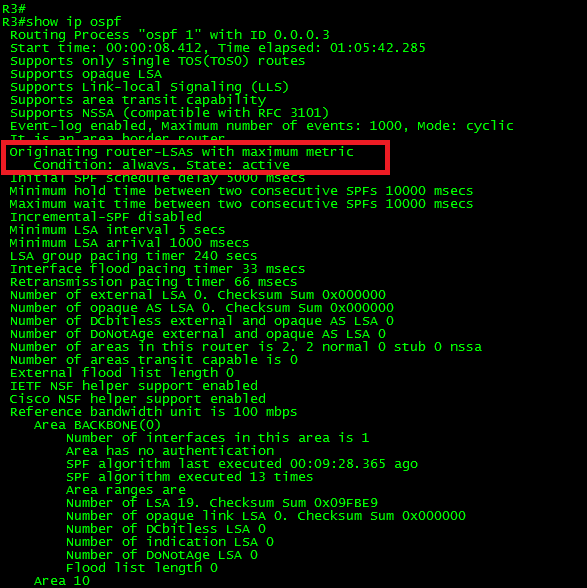
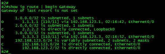
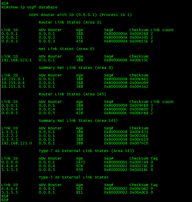
First, let’s take a look to the routing table in R4:

OSPF-FILTERING-3-02

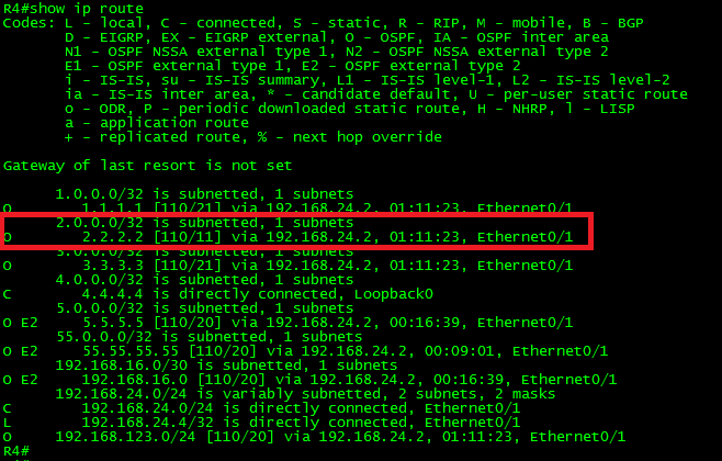
As can be seen in the above output, the route 2.2.2.2/32 is in the routing table.  It is displayed as an “O” OSPF route, meaning that it was advertised from another OSPF-enabled router within the same area (intra-area).   From this output, we can conclude that the prefix was advertised via a Type-1 (Router) LSA.

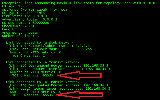
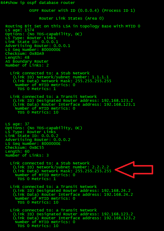
Just as a reference, let’s take a look to the Type-1 (Router) LSA:

OSPF-FILTERING-3-03

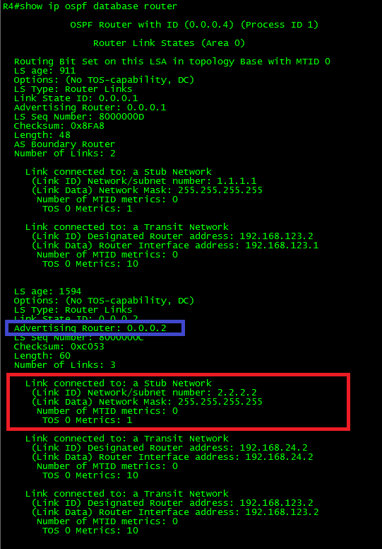
As can be seen in the output, the LSA has 3 link advertisements enclosed.  One LSA corresponds to the Stub Network 2.2.2.2/32 and the last two corresponds to the Transit Networks.

Ok, because the advertising router 0.0.0.2 (R2) is placed in the same area, the only possible filtering option is by using distribute-list in the inbound direction.

So, let’s apply the filter using a simple ACL.

In R4:

!
access-list 2 deny   2.2.2.2
access-list 2 permit any
!
router ospf 1
distribute-list 2 in
exit
!

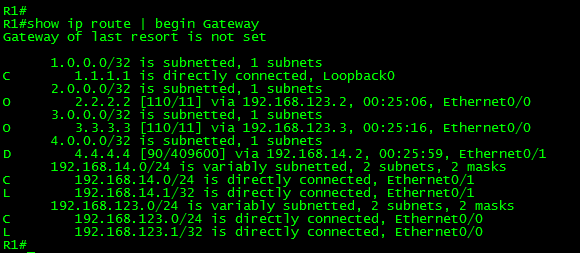
Now, let’s take a look at the routing table of R4:

OSPF-FILTERING-3-04

As can be seen in the output, the route is no longer present.  What about the LSDB?  What was the effect of the filter in there?

OSPF-FILTERING-3-05

As can be seen, the Type-1 LSA is still there.   There was no effect on the LSDB.   Now let’s take a look to the OSPF RIB:

OSPF-FILTERING-3-06

Have you noticed the difference?  Yes, the “greater than symbol” next to the route.  This means the route is present but it wasn’t marked as Best.   Thus, the route is not installed in the Router’s RIB.

Now, we could achieve the same result by using extended ACLS.

Let me show you a trick.    Not long ago I was requested to filter a specific route, the same way it was done before.   However, the request also has included one very specific requirement as well.  The filter must apply only over business hours, Monday thru Friday from 7:00 am to 7:00 pm.

Here goes how to do it:   (This requires time synchronization.)

  1. Create a Time-Based ACL.
  2. Apply the distribute-list referencing the Time-Based ACL.

In R4:

!
time-range NO-ACCESS
periodic weekdays 7:00 to 19:00
!
access-list 102 deny   ip any host 2.2.2.2 time-range NO-ACCESS
access-list 102 permit ip any any
!
router ospf 1
distribute-list 102 in
exit
!

Another way to do it is by using prefix-lists:

In R4:

!
ip prefix-list NO-LO-R2 seq 10 deny 2.2.2.2/32
ip prefix-list NO-LO-R2 seq 20 permit 0.0.0.0/0 le 32
!
router ospf 1
distribute-list prefix NO-LO-R2 in
exit
!

Another possible thing we can do with distribute-list is matching the source of the route.  To clarify this, by the source of the route I mean the gateway used to reach the route to be filtered.

Let’s make a small change to the topology for this:

OSPF-FILTERING-3-07

Let’s add the link in red and remove any configured filtering.

The link configurations are as follows:

In R3:

!
interface Ethernet0/2
ip address 192.168.34.3 255.255.255.0
ip ospf 1 area 0
!

In R4:

!
interface Ethernet0/2
ip address 192.168.34.4 255.255.255.0
ip ospf 1 area 0
!

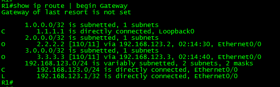
Ok, now let’s take a look at the routing table in R4:

OSPF-FILTERING-3-08

As can be seen in the above output, by adding this link, R4 has now two equal cost paths to reach networks beyond the transit network 192.168.123.0/24.

Goal 2:

Apply filtering in such way that the Loopback0 in R1 be can be reached from R4 only thru R2.

Ok, so far we know the route to 1.1.1.1/32 (Loopback 0 in R1) is being load-balanced.   This is because OSPF is doing ECMP (Equal Cost Multi-Path) between R2 and R3.   What we must do is filtering only the route through R3.

There are two ways to achieve this.   One applying the distribute-list using one of the different ways we have learned so far (access-list, extended ACL, named ACL or prefix-list) and specify the interface from where is learning the route.

Let’s try it this way:

For this example, I would use a named ACL.

In R4:

!
ip access-list standard R1_Loopback0
deny   1.1.1.1
permit any
!
router ospf 1
distribute-list R1_Loopback0 in Ethernet0/2
!

Now, let’s take a look at the routing table in R4 and to the details of the OSPF RIB for that particular route:

OSPF-FILTERING-3-09

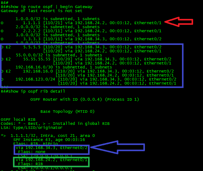
As can be seen in the above output, the route to 1.1.1.1/32 is now reachable only via R2.  The rest of the routes remain to be load-balanced.    Also, take a look to the OSPF RIB.   Both routes are present.   However, the one with the arrow in blue through R3 has no RIB flag, while the other route, thru R2, has it.    Only the route in green was installed into the Router’s routing table.

The other way to achieve this goal is by using Route-Maps.   Route-Maps provide more flexibility than ACLS or Prefix-Lists.   With route-maps we can match multiple options such:

  • match interface
  • match ip {address|next-hop|route-source}
  • match metric
  • match route-type {internal|external [type-1|type-2] | nssa-external [type-1|type-2]}
  • match tag

We could achieve the same result by using the following configuration:

In R4:

!
ip prefix-list Filter-R1-L0 seq 5 permit 1.1.1.1/32
!
route-map FILTER->RIB deny 10
match ip address prefix-list Filter-R1-L0
match interface Ethernet0/2
!
route-map FILTER->RIB permit 100
!
router ospf 1
distribute-list route-map FILTER->RIB in
exit
!

I think that you get the idea.

Now, why have I mentioned that we must be careful when using this command?

I will use another example to illustrate why.  Let’s use the original topology, without any filtering.

OSPF-FILTERING-3-01


Goal 3:

Filter the route to 1.1.1.1 only in R2.

It seems a fairly simple task now that we know how to do it.   So let’s apply the filter in R2.

In R2:

!
access-list 1 deny   1.1.1.1
access-list 1 permit any
!
router ospf 1
distribute-list 1 in
exit
!

Now let’s take a look at the routing table in R2:

OSPF-FILTERING-3-10

Ok, as shown in the above output, seems that it worked.  The route to 1.1.1.1 is no longer in the routing table of R2.

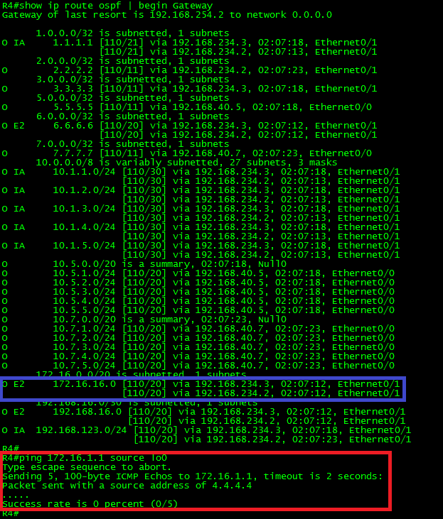
Let’s say it’s the last trouble ticket of the day.  Then we proceed to turn off the computer and drive back home.   That’s it for the day.

An hour later, we receive a phone call reporting problems to reach 1.1.1.1 from R4.

OSPF-FILTERING-3-11

But, wait a minute!  We did not make any change to R4.  Do we?

As a matter of fact, yes indirectly we did it. We have created a black hole in the network.

Let me explain this.

When we apply the filter to the route 1.1.1.1, it was applied directly to the routing table.  The LSDB was not altered.  R4 has received an LSA from R2 containing information how to reach 1.1.1.1, thus, R4 has installed the route in its routing table.

Guess what is the next-hop to reach 1.1.1.1 from R4?   Yes.  It’s the same next-hop used to reach any other network, R2.

Now you know why OSPF RIB filtering must be used carefully.   This was just an example, but what if we make the same mistake to a high sensitive area of the production network?   This could be a Resume Generating Event.

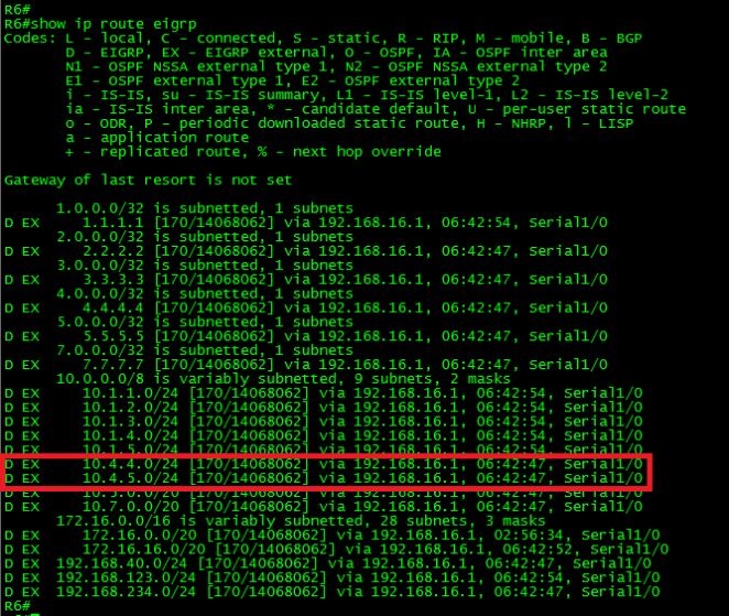
Using the distribute-list command in the outbound direction:

As mentioned before, using the distribute-list command in the outbound direction filters only the redistributed routes.   Meaning that is used only on ASBR’s.

Goal 4:

Prevent the route to 55.55.55.55/32 from being advertised beyond R1.

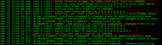
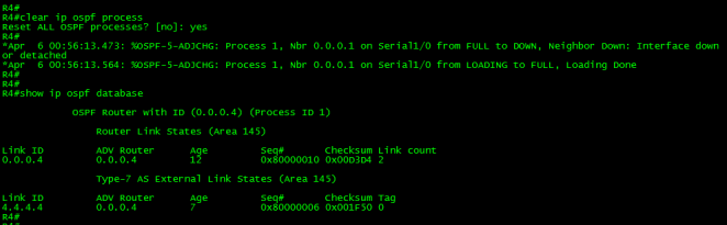
Let’s turn on the debug ip ospf lsa-generation for this example.

In R1:

!
debug ip ospf lsa-generation
!
configure terminal
!
access-list 55 deny   55.55.55.55
access-list 55 permit any
!
router ospf 1
distribute-list 55 out
exit
!

Let’s take a look at the output of the debug.

OSPF-FILTERING-3-12

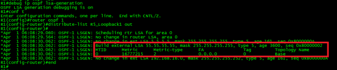
Immediately after applying the filter, R1 generated a Type-5 LSA with the max-age set (3600 seconds).  Remember, LSAs with max age set are discarded.  Also, note the metric was set to 16777215.  This is the maximum metric for routes in the OSPF database in decimal.  A route with this metric is inaccessible therefore is discarded from the OSPF database.  This metric is also known as LSInfinity.   The result is the filtering of the desired route from the OSPF domain.

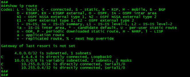
Let’s confirm this by looking the routing table in R4:

OSPF-FILTERING-3-13

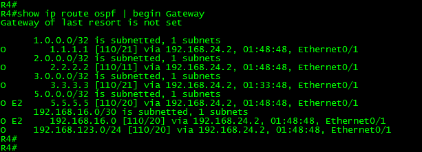
As can be seen in the above output, the filtering worked as expected.   The route to 55.55.55.55/32 is not present in the routing table.

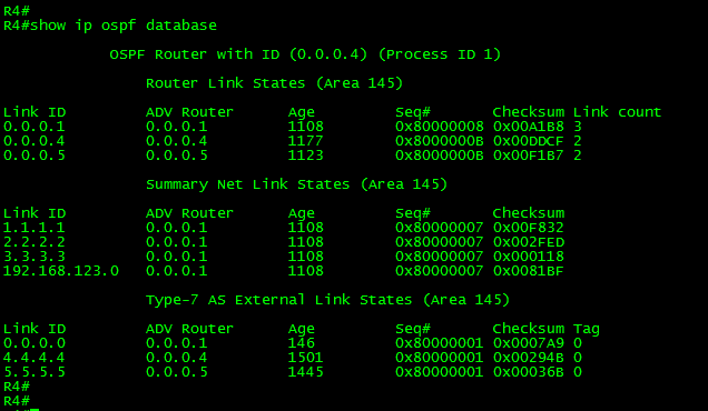
There is one last thing to mention in regards to filtering.  It has to do with NSSA areas.

Let’s modify a little bit the topology:

OSPF-FILTERING-3-14


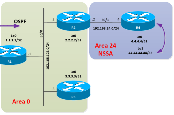
Let’s put R4 into an NSSA area and create loopback1, let’s redistribute it into the process.  Let’s also remove any filtering in R2.

In R2:

!
router ospf 1
area 24 nssa
!
interface Ethernet0/1
ip ospf 1 area 24
!

In R4:

!
interface Loopback0
ip ospf 1 area 24
!
interface Loopback1
ip address 44.44.44.44 255.255.255.255
!
route-map CONN-LOOPBACKS->OSPF permit 10
match interface Loopback1
!
router ospf 1
area 24 nssa
redistribute connected subnets route-map CONN-LOOPBACKS->OSPF
exit
!

With this configuration applied, R4 has generated and flooded a Type-7 LSA within the area, corresponding to the redistributed route. R2 (ABR) received the Type-7 LSA with the P-bit set; R2 then has generated a Type-5 LSA and start advertising the redistributed route on behalf of R4.

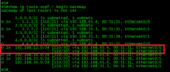
Let’s take a look at the routing table in R2, just to confirm that the route is there.

OSPF-FILTERING-3-15

Ok, the route was installed. Now, let’s apply filtering to 4.4.4.4 (Loopback0) in R2.

In R2:

!
ip access-list standard R4_L0
deny   4.4.4.4
permit any
!
router ospf 1
distribute-list R4_L0 in
exit
!

Finally, let’s take a look at the routing table in R2 and take a look at the results:

OSPF-FILTERING-3-16

Ok, the filtering didn’t work as expected.   The route to 4.4.4.4/32 was filtered, but also, the route to the redistributed 44.44.44.44/32 was removed from the routing table.

So, what happened here?

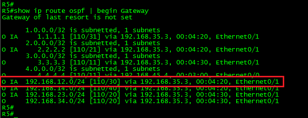
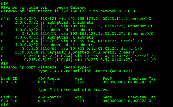
First, let’s take a look to the LSDB and then to the OSPF RIB in R2:

OSPF-FILTERING-3-17

Ok, as can be seen in the above output, the Type-7 LSA is there, the route 4.4.4.4/32 was filtered in the OSPF RIB (It doesn’t have the greater than symbol or RIB flag).  Also, the route 44.44.44.44/32 is not present in the OSPF RIB.

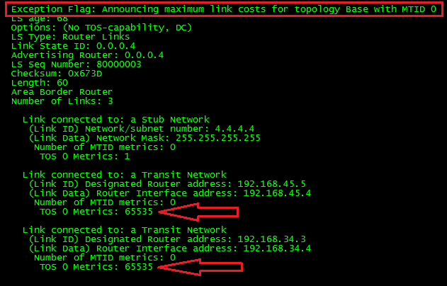
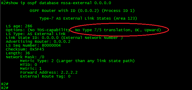
Now, let’s take a look to the Type-7 LSA and try to figure out what the problem is.

OSPF-FILTERING-3-18


Ok, did you find the problem?

The P-bit is there.  Meaning the translation from Type-7 to Type-5 must take place.   That is not the problem.   What about the forward address?   Yup, you got it.   At the moment we filter 4.4.4.4, the route finds itself without next-hop.  Thus, the LSA was discarded.

The problem has to do with the way NSSA advertise redistributed routes.  NSSA choose the forwarding address as follows:

It chooses the highest IP address of an internal address; if an internal address is not available, it will prefer the higher found OSPF stub network.

It is good to emphasize that although filtering the OSPF RIB sometimes seems a good idea, in some cases; it may lead to undesired behaviors and in extreme cases may end in self-inflicted denial of service.   So, use it carefully.

It is time to close this long post. In the next one, we will continue discussing OSPF Filtering but, this time, using Administrative Distance.

Thank you for visiting.

OSPF Filtering with Summarization

In today’s post, we will continue discovering the different ways we can perform filtering in OSPF.

Previously we depict two common ways to filter routes in OSPF, the first one using LSA Type-3 filtering and the second was filtering NSSA external routes directly to the redistribution process in OSPF.   Worth mentioning that for the second example in the previous post (Goal 2) I did a change in the original configuration.   This was done just to illustrate a way to instruct OSPF to not to impose the P-bit into the redistributed routes.   However this effect could be achieved by doing a simpler change which will help us to introduce the third OSPF filtering type:

Filtering with Summarization

This type of filtering as its name implies works in conjunction with OSPF Summarization.  The idea behind this type of filtering is done by grouping a set of prefixes by using summarization and then suppress the newly generated LSA propagation adding the not-advertise keyword.

Let’s use the previous network topology for the examples.   (Please note the addition of Loopbacks 16 to 18 in R6).

OSPF-FILTERING-2-01

Here you can download the diagram and configuration files: OSPF-Filtering – Part II

Let’s take a look to the routing table from the perspective of R4, but let’s focus on the routes coming from the EIGRP domain:

OSPF-FILTERING-2-02

Ok, so far we know the prefixes 172.16.1.0/24 to 172.16.10.0/24 and 172.16.16.0/24 to 172.16.18.0/24 are being redistributed from R6 (EIGRP domain) into OSPF in R1 and then Summarized into a single /16 supernet.  This redistribution makes R1 an ASBR.  We also know R1 is placed into an NSSA area.   This means the routes were originally advertised as Type-7 LSAs by R1 and then translated into Type-5 LSAs by one of the ABRs connecting the NSSA and flooded into Area 0 and from there to the rest of the OSPF domain.

Having this information on hand, let’s play a little bit with Filtering with summarization.

Goal 1:

Summarize the routes coming from the EIGRP domain into two /20 supernets (172.16.0.0/20 and 172.16.16.0/20).  Apply filtering in such way that the network 172.16.0.0/20 only be accessible from R1, the second segment can be reached from anywhere in the network.

Ok, the task is very straightforward.  What we should do is remove the previous summarization and generate two summary routes; however one of the summary routes should not be advertised.  This can be achieved by adding the not-advertise keyword to the summary route at which we want to apply the filter.    Now, I would like to demonstrate the effect in the LSDB of adding the keyword after the summary route was created.   So, let’s do it.

In R1 (ASBR):

!
router ospf 1
no summary-address 172.16.0.0 255.255.0.0
summary-address 172.16.0.0 255.255.240.0
summary-address 172.16.16.0 255.255.240.0
exit
!

Let’s take a look at the Link-State Database (LSDB) in R1, specifically the Type-7 AS External LSAs:

OSPF-FILTERING-2-03

As can be seen in the above output, now we have two summary Type-7 LSAs.   Also, note the LSAs have the P-Bit set (In blue).   This will trigger the translation between Type-7 into Type-5 LSAs in the ABR.   Both summary routes will be advertised to the OSPF domain.

The last part of the goal requires filtering the first range.   So, to apply the filter, just add the not-advertise keyword to the desired summary-address command.

Before adding the filter let’s debug the ospf lsa-generation and observe the changes:

OSPF-FILTERING-2-04

I never get tired of repeating that the use of any debug must be done with extreme caution.

As can be seen in the above output, after the changes were applied R1 generated an external LSA for the network 172.16.0.0/20 with LS age set to 3600 seconds which is the max age.  The LSA metric was set to 16777215 or (max-metric for routes in the OSPF database) LSInfinity.  When the max age timer on an LSA reaches 60 minutes, the LSA is discarded.    The result is: Yes, the filtering of the summary network 172.16.0.0/20.

OSPF-FILTERING-2-05

As seen in the above output, the filter worked as expected.   This solution is suitable for this particular situation, where only the network in R1 needs the access.   They will use the EIGRP routes for this purpose.

OSPF-FILTERING-2-06

However, these routes will not be reachable from anywhere else in the OSPF domain as can be seen next.

OSPF-FILTERING-2-07

As can be seen in the above output, the networks are reachable from the desired points of the network, the traffic flows accordingly; the network is stable, and the goal was achieved.

After a few days, we have received the following information:

“Within the following weeks, some new network segments will be created in R2 and R3 for Servers connected to Area 30.   This change will require allowing access to the network 172.16.0.0/20 in the EIGRP domain from Area 30.”

OSPF-FILTERING-2-08

In this case, the filtering solution provided before will not work.  To achieve this will be required to allow the advertisement of the summary networks to R2 and R3 respectively and stop the advertisement there.

This requirement is similar to Goal 2 of the previous post.  So, let’s do it.

Goal 2

Apply OSPF filtering to the summary route 172.16.0.0/20 in such way this network only be accessible from AREA 30.  The second segment can be reached from anywhere in the network.

Let’s recap a bit what we did to solve it in the last post.   What it was done was removing the summarization of the route in question, and then apply filtering directly into the redistribution process using the keyword NSSA-only.

In this case, the given solution in the previous post won’t work.  This is because we have two summary routes from which only one has to be filtered.

Luckily OSPF provides the same functionality when summarizing external routes in Not-so-Stubby-Areas, meaning that we can use the keyword NSSA-only, and at the same time suppress the P-bit from being imposed.    The direct result will be the no translation from Type-7 to Type-5 LSAs in the ABR, thus, the desired summary route won’t be advertised beyond Area 30.

Let’s make the change and take a look to the external type-7 LSAs in R1:

In R1 (ASBR):

!
router ospf 1
no summary-address 172.16.0.0 255.255.240.0 not-advertise
summary-address 172.16.0.0 255.255.240.0 nssa-only
exit
!

OSPF-FILTERING-2-09

As can be seen in the above output, now R1 has generated Type-7 LSAs for both summary routes.   But if you look (in blue) the options field for each one, the first LSA has the Type7/5 bit imposed while the other says No Type 7/6 translation.    In other words, only the LSA with the P-bit set will be translated to Type-5 LSA in the ABR and flooded into Area 0.

Let’s take a look from the perspective of R2:

OSPF-FILTERING-2-10

As shown in the above output, in R2 we can find Type-7 LSAs for both prefixes but note (in blue) there is only one Type-5 LSA.   This confirms the change.   Only the LSA corresponding to the prefix 172.16.16.0/20 was translated into Type-5.    For brevity, I’m showing only R2, but it is the same output from both ABRs.  (If you look closer to the Type-5 LSAs, the advertising router is R3.   This is because the Type-7/5 translator is R3.  Thus, R3 was the one advertising the generated Type-5 LSAs to R2.)

Now, from R2 and R3 we can find both routes as “O N2” or OSPF NSSA external type 2 routes, meaning that both summary routes can be reached from Area 30 as shown in the next output:

OSPF-FILTERING-2-11

Finally, let’s check the changes from R4’s perspective:

OSPF-FILTERING-2-12

As can be seen, the goal was achieved, only the subnet 172.16.16.0/20 from the EIGRP is reachable from there.   What about the routers in Area 40?  They don’t have individual routes for external networks.   Stub areas generate the default route in OSPF by default, being the ABR the next-hop to reach external networks, thus they rely on R4 to route the traffic.  Therefore, they won’t be able to reach the filtered routes either.

After a few weeks a new request is received:

“The traffic from Area 30 and the EIGRP domain to the segments 10.4.1.0/24 to 10.4.3.0/24 must be filtered.”

Ok, let’s get started.

Goal 3

Apply OSPF filtering in such way that eastbound traffic from R1 towards 10.4.1.0/24 to 10.4.3.0/24 be unreachable; all other networks must work as usual.

Let’s start looking at the traffic path from R1’s perspective:

OSPF-FILTERING-2-13

As can be seen in the above output, the desired traffic is been load-balanced via R2 and R3.

We know that R2 and R3 are ABRs, and we also know that we can summarize the desired networks into 10.4.0.0/22.   Then OSPF filtering with summarization can be a suitable solution.

So in order to achieve the goal, we have to apply the filter into both ABRs.   If we apply it to only one of them, the result will be…  Yes, you got it, some sort of Traffic Engineering.

OSPF-FILTERING-2-14

So let’s start by applying the filter into the first ABR.

Remember, to filter the summary route, just add the not-advertise keyword to the summarization command.   Also remember, when doing summarization, in ABRs the command area {area-source} range {network-id} {subnet-mask} OSPF process command is used; where {area-source} as its name implies, is from which area is the router receiving the desired LSAs.

In R2 (ABR):

!
router ospf 1
area 0 range 10.4.0.0 255.255.252.0 not-advertise
exit
!

With this change applied only in R2, the summary route 10.4.0.0/21 won’t be advertised to R1, but the individual routes will by reachable via R3 as shown below:  (Traffic Engineering effect.)

OSPF-FILTERING-2-15

Finally, the only missing part of achieving the goal is applying the same filter into R3 ABR.

In R3 (ABR):

!
router ospf 1
area 0 range 10.4.0.0 255.255.252.0 not-advertise
exit
!

Let’s take a look now to the routing table in R1 and R6 (EIGRP domain):

OSPF-FILTERING-2-16

OSPF-FILTERING-2-17

As can be seen, now only the routes to 10.4.4.0/24 and 10.4.5.0/24 from R4 are present in the routing tables of R1 and R6.

Let me explain why:

When we apply the command area 0 range 10.4.0.0 255.255.252.0 not-advertise on both ABRs, they have generated and flooded a Type-3 LSA corresponding to the summary address with the LS age set to its max value (3600 seconds) and the metric set LSInfinity.  Therefore, these LSAs were discarded within Area 30.   Subsequently, the routes were no longer redistributed into the EIGRP domain.

It is time to close this long post.  In the next one, we will continue discussing OSPF Filtering but this time using Distribute-Lists.

Thank you for visiting.